- 您现在的位置:买卖IC网 > Sheet目录299 > 71M6543F-IGT/F (Maxim Integrated Products)IC ENERGY METERING
�� �
�
�71M6543F/71M6543G� Data� Sheet�
�Delay� compensation� and� other� functions� in� the� CE� code� require� the� settings� for� MUX_DIV[3:0],�
�MUXn_SEL[3:0],� RMT_E,� FIR_LEN[1:0],� ADC_DIV� and� PLL_FAST� to� be� fixed� for� a� given� CE� code.�
�Refer� to� Table� 1� and� Table� 2� for� the� settings� that� are� applicable� to� the� 71M6543.�
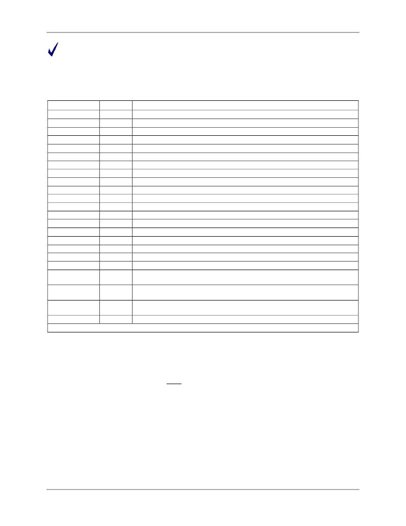
�Table� 3� summarizes� the� I/O� RAM� registers� used� for� configuring� the� multiplexer,� signals� pins,� and� ADC.� All�
�listed� registers� are� 0� after� reset� and� wake� from� battery� modes,� and� are� readable� and� writable.�
�Table� 3:� Multiplexer� and� ADC� Configuration� Bits�
�Name�
�MUX0_SEL[3:0]�
�MUX1_SEL[3:0]�
�MUX2_SEL[3:0]�
�MUX3_SEL[3:0]�
�MUX4_SEL[3:0]�
�MUX5_SEL[3:0]�
�MUX6_SEL[3:0]�
�MUX7_SEL[3:0]�
�MUX8_SEL[3:0]�
�MUX9_SEL[3:0]�
�MUX10_SEL[3:0]�
�ADC_DIV�
�MUX_DIV[3:0]�
�PLL_FAST�
�FIR_LEN[1:0]�
�DIFF0_E�
�DIFF2_E�
�DIFF4_E�
�DIFF6_E�
�RMT2_E�
�RMT4_E�
�RMT6_E�
�PRE_E�
�Location�
�2105[3:0]�
�2105[7:4]�
�2104[3:0]�
�2104[7:4]�
�2103[3:0]�
�2103[7:4]�
�2102[3:0]�
�2102[7:0]�
�2101[3:0]�
�2101[7:0]�
�2100[3:0]�
�2200[5]�
�2100[7:4]�
�2200[4]�
�210C[2:1]�
�210C[4]�
�210C[5]�
�210C[6]�
�210C[7]�
�2709[3]�
�2709[4]�
�2709[5]�
�2704[5]�
�Description�
�Selects� the� ADC� input� converted� during� time� slot� 0.�
�Selects� the� ADC� input� converted� during� time� slot� 1.�
�Selects� the� ADC� input� converted� during� time� slot� 2.�
�Selects� the� ADC� input� converted� during� time� slot� 3.�
�Selects� the� ADC� input� converted� during� time� slot� 4.�
�Selects� the� ADC� input� converted� during� time� slot� 5.�
�Selects� the� ADC� input� converted� during� time� slot� 6.�
�Selects� the� ADC� input� converted� during� time� slot� 7.�
�Selects� the� ADC� input� converted� during� time� slot� 8.�
�Selects� the� ADC� input� converted� during� time� slot� 9.�
�Selects� the� ADC� input� converted� during� time� slot� 10.�
�Controls� the� rate� of� the� ADC� and� FIR� clocks.�
�The� number� of� ADC� time� slots� in� each� multiplexer� frame� (maximum� =� 11).�
�Controls� the� speed� of� the� PLL� and� MCK.�
�Determines� the� number� of� ADC� cycles� in� the� ADC� decimation� FIR� filter.�
�Enables� the� differential� configuration� for� analog� input� pins� IADC0-IADC1� .�
�Enables� the� differential� configuration� for� analog� input� pins� IADC2-IADC3� .�
�Enables� the� differential� configuration� for� analog� input� pins� IADC4-IADC5� .�
�Enables� the� differential� configuration� for� analog� input� pins� IADC6-IADC7� .�
�Enables� the� remote� sensor� interface� transforming� pins� IADC2-IADC3� into� a� digital�
�interface� for� communications� with� a� 71M6xx3� sensor.�
�Enables� the� remote� sensor� interface� transforming� pins� IADC4-IADC5� into� a� digital�
�interface� for� communications� with� a� 71M6xx3� sensor.�
�Enables� the� remote� sensor� interface� transforming� pins� IADC6-IADC7� into� a� digital�
�interface� for� communications� with� a� 71M6xx3� sensor.�
�Enables� the� 8x� pre-amplifier.�
�Refer� to� Table� 70� starting� on� page� 102� for� more� complete� details� about� these� I/O� RAM� locations.�
�2.2.3�
�Delay� Compensation�
�When� measuring� the� energy� of� a� phase� (i.e.,� Wh� and� VARh)� in� a� service,� the� voltage� and� current� for� that�
�phase� must� be� sampled� at� the� same� instant.� Otherwise,� the� phase� difference,� Ф,� introduces� errors.�
�φ� =�
�t� delay�
�T�
�?� 360� o� =� t� delay� ?� f� ?� 360� o�
�The� “constant� delay”� all-pass� filter� provides� a� broad-band� delay� 360� -� θ,� which� is� precisely� matched� to�
�Where� f� is� the� frequency� of� the� input� signal,� T� =� 1/f� and� t� delay� is� the� sampling� delay� between� current� and�
�voltage.�
�Traditionally,� sampling� is� accomplished� by� using� two� A/D� converters� per� phase� (one� for� voltage� and� the�
�other� one� for� current)� controlled� to� sample� simultaneously.� Maxim’s� Single� Converter� Technology,�
�however,� exploits� the� 32-bit� signal� processing� capability� of� its� CE� to� implement� “constant� delay”� all-pass�
�filters.� The� all-pass� filter� corrects� for� the� conversion� time� difference� between� the� voltage� and� the�
�corresponding� current� samples� that� are� obtained� with� a� single� multiplexed� A/D� converter.�
�o�
�the� difference� in� sample� time� between� the� voltage� and� the� current� of� a� given� phase.� This� digital� filter� does�
�not� affect� the� amplitude� of� the� signal,� but� provides� a� precisely� controlled� phase� response.�
�v2�
�19�
�发布紧急采购,3分钟左右您将得到回复。
相关PDF资料
71M6545-IGT/F
IC ENERGY METERING
720-10007-00300
CBL D-SUB 9PIN FMAL-25PIN FML 3M
720-10010-00025
CBL DSUB 9PIN FML-25PIN MAL .25M
720-10020-00300
CBL DSUB 9PIN FML-9PIN MALE 3M
720-10021-00300
CBL DSUB 9PIN FML-9PIN FEMAL 3M
72231-0881
8 POS T/P SHLD 4 GR ASSY
7250B
PANEL KIT BOTTOM FOR R-1220 CASE
731-10061-00200
CBL DSUB HD 15FEMAL-15MALE 2.0M
相关代理商/技术参数
71M6543F-IGTR/F
功能描述:计量片上系统 - SoC Precision Energy Meter IC
RoHS:否 制造商:Maxim Integrated 核心:80515 MPU 处理器系列:71M6511 类型:Metering SoC 最大时钟频率:70 Hz 程序存储器大小:64 KB 数据 RAM 大小:7 KB 接口类型:UART 可编程输入/输出端数量:12 片上 ADC: 安装风格:SMD/SMT 封装 / 箱体:LQFP-64 封装:Reel
71M6543FT-IGT/F
制造商:Maxim Integrated Products 功能描述:ENERGY METER ICS - Rail/Tube
71M6543FT-IGTR/F
制造商:Maxim Integrated Products 功能描述:3-PHASE SOC, 64KB FLASH, PRES TEMP SENSOR - Tape and Reel
71M6543G
制造商:MAXIM 制造商全称:Maxim Integrated Products 功能描述:Selectable Gain of 1 or 8 for One Current Energy Meter ICs Metrology Compensation
71M6543GH
制造商:未知厂家 制造商全称:未知厂家 功能描述:电表IC
71M6543GHT-IGT/F
制造商:Maxim Integrated Products 功能描述:3-PHASE, 128KB, PRES TEMP SENSOR, HI PREC - Bulk
71M6543GHT-IGTR/F
制造商:Maxim Integrated Products 功能描述:3-PHASE, 128KB, PRES TEMP SENSOR, HI PREC - Tape and Reel
71M6543G-IGT/F
功能描述:计量片上系统 - SoC Precision Energy Meter IC RoHS:否 制造商:Maxim Integrated 核心:80515 MPU 处理器系列:71M6511 类型:Metering SoC 最大时钟频率:70 Hz 程序存储器大小:64 KB 数据 RAM 大小:7 KB 接口类型:UART 可编程输入/输出端数量:12 片上 ADC: 安装风格:SMD/SMT 封装 / 箱体:LQFP-64 封装:Reel